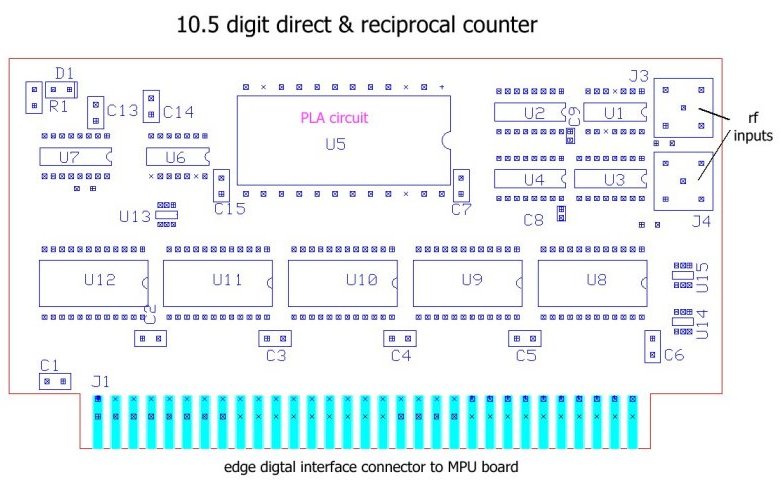
The BH5314F2 is a 10 ½-stage direct and reciprocal counter board with two rf inputs, gate circuits
and output latches. The counter is build around PLA circuit with some additional TTL ands CMOS circuits.
The card has two inputs F1 and F2 for measured signals, a gate input
and two independent start / stop inputs. All of these inputs use coaxial
connectors. The latch output signals and control board input signals are made
via an edge connector. All input signals and latch outputs have a TTL
level. The entry circuit accept signals up to at least 125 MHz from input
rf amplifier BH4116A or similar.
The control signals set up four main measurement functions:
- frequency F1
- period F1
- ratio F1 / F2
- start - stop counting
With a small option board is a function F1-F2 (substraction two input signals) available.
Since the BH5314A accepts signals above 100 MHz, the period can be measured
with a resolution of 10 ns (for OCXO 100 MHz) if Timebase BH5315A
is used. Various gate signals
from 10 sec to 1 ms are available for frequency measurement. Also precise RPM
measurement with gate 60 sec is available.
The start-stop function counts the signal supplied by the gate input. If
Time Base BH5315A is used, the counted signals can be
supplied either from OCXO or from external sources.
The counter board is powered via edge connector with ±5V.
The Printed Circuit Board has four layers and size 6" x 2.2" (153 x 56 mm)
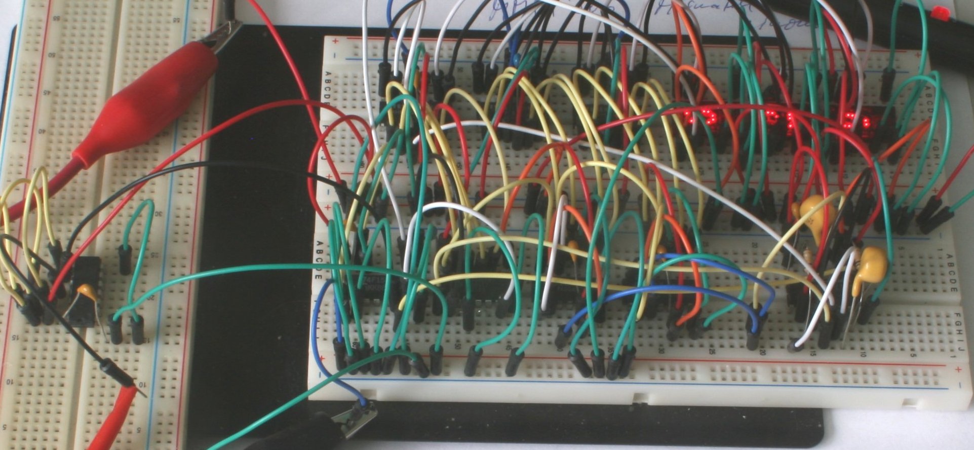
Test of gate circuits and the first three decades (LSD, LSD + 1 and LSD + 2) on breadboard: