This is an universal time board that generates various time signals that are
suitable for test interuments.
The clock source used is high-precision VCXO either 10 MHz or 100 MHz,
which can be set from the voltage reference. However, an external 10 MHz clock signal from Rubidium or
Cesium standards or from GPS can override the signal from the local VCXO.
Switching between the signal from the local 10 or 100 MHz VCXO and the external source
is automatic. Once the external signal is applied to the input port, local
circuit switches to more accurate signal.
In addition to the external 10 MHz signal, the Time Base card also accepts two
other GPS signals: 10 kHz and 1 PPS signal. Both can be used for synchronization.
The time base board has two external synchronisation inputs for signals from 1 Hz up
to 50 Mhz with levels from 10 mV to 6V. Each signal is controlled separately
with control signal via edge connector.
Clock Signals available from Time Board:
Buffered 10 or 100 MHz signal from local VCXO, 1 MHz, 100 kHz, 10 kHz, 1 kHz, 100 Hz,
50 Hz, 10 Hz, 5 Hz, 1 Hz, 10 sec and 60 sec.
Most of signals can be prolonged by 1:4 or 1:8 or 1:16. All signals have TTL level.
Signals are selectable by 6-bits word via Edge Connector. Other control signals
such as reset and some other dedicated control signals are available on the
edge connector for test instruments such as counters, word generators, signal
generators, etc.
Time Board is powered via edge connector with ±5V.
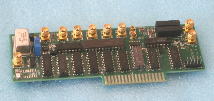
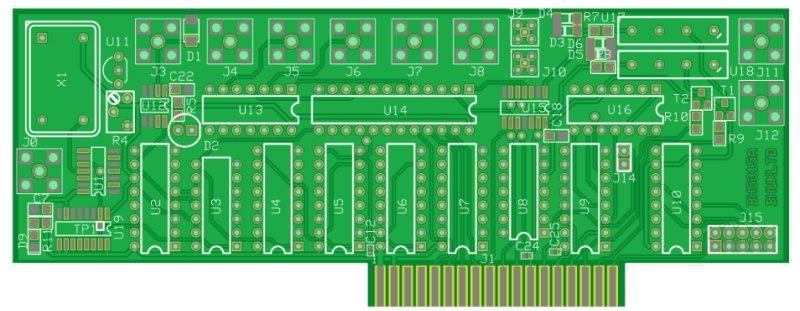
Documentation
The Printed Circuit Board has size 5.7" x 2.2" (145 x 56 mm)