This project, a high precision 10 MHz OCXO frequency standard with integrated digital
clock (code JPL-570A) was made in Nov 2008. The instrument is built around 5 ppm TCXO and external CMOS logic circuits.
No CPU or MCU are used. Beside a standard sinewave 10 MHz output are several derived
clock signals available.
Clock
Figure 1 (see schematics) shows the clock circuit based on PLA. The clock circuit has output to six
multiplexed digits and is drived from main and secondary oscillator. The secondary
oscillator (25ppm) is switched automatically on if power failure. The secondary oscillator has
less power consuption, unlike its precision is only 25ppm.
Display
The clock display is build with four common cathode 0.8-inch size LEDs and two 0.4-inch size LEDs.
Power Supply
Figure 3 (see schematics) shows power supply for frequency standard, TCXO with logic and digital clock.
The power supply has multiple voltage outputs, power line detector, battery switcher
and battery charger and Power On Reset signal generator.
The instrument is powered from external line power supply. If power supply is down,
the line detector send a signal and the instrument is powered from battery. In this
case, the LED display is off and main oscillator is replaced with secondary oscillator.
If line is restored, the LED display is on and main oscillator is in restarted.
The battery is continuously monitored and charged. The battery backup time is approx.
14 hours.
Construction
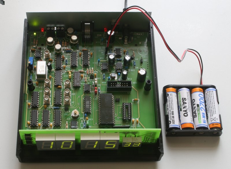
The photo shows the construction. The system can be expanded (i.e. external interface,
etc.), with a microcontroller through a feature connector. However, the basic test
instument doesn't need a microcontroller.
The instrument measures 150 x 50 x 180 mm. Power consumption is about 4 Watt.
Backup battery are four NiMH cells size AA with capacity of 2.7Ah.
Documentation