Electronic Circuits & Components Tester
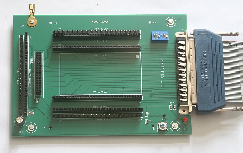
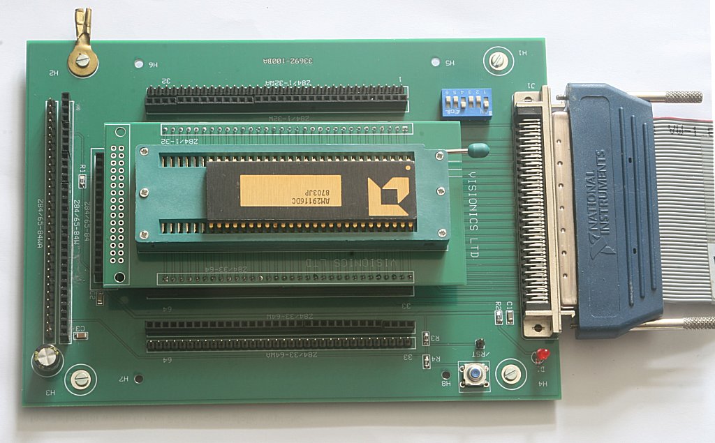
This electronics circuit and component tester can test all electronic circuits, not just integrated or digital ones, but also more complex circuits and analog circuits. It can also test various electronic components. The electronics circuit and component tester is a multi-board testing device. The most important part of the electronics circuit and component tester is the main board. It connects the circuits between the circuit adapter and a host computer.
Fig. 1 - Electronic Circuits and Components Tester Mainboard
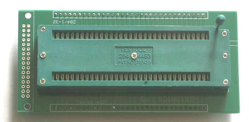
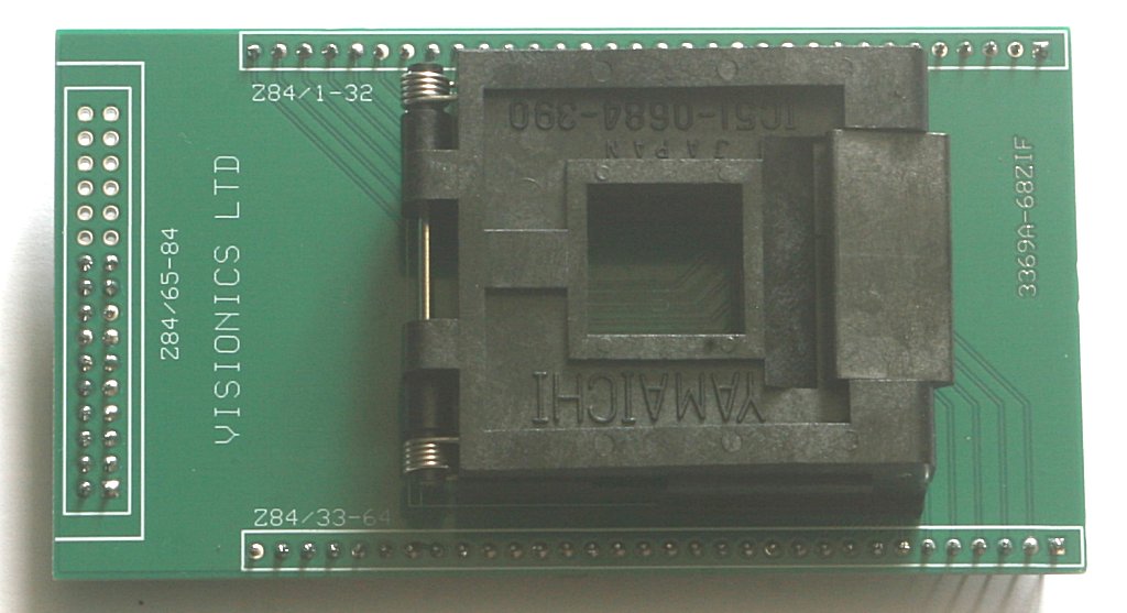
The connection to the host computer is realized with either 2x 50-wires flat cable or with 100-wires shielded cable. Both cables are made by National Instruments. Only 96 wires are used to test the circuit. Connection to the DUT is made by various adapter. The adapters are more or less universal. Standard adapters with ZIF42, ZIF64, or ZIF68 are more versatile and make it easy to connect many digital circuits quickly.
Fig. 2 - ZIF64 adapter
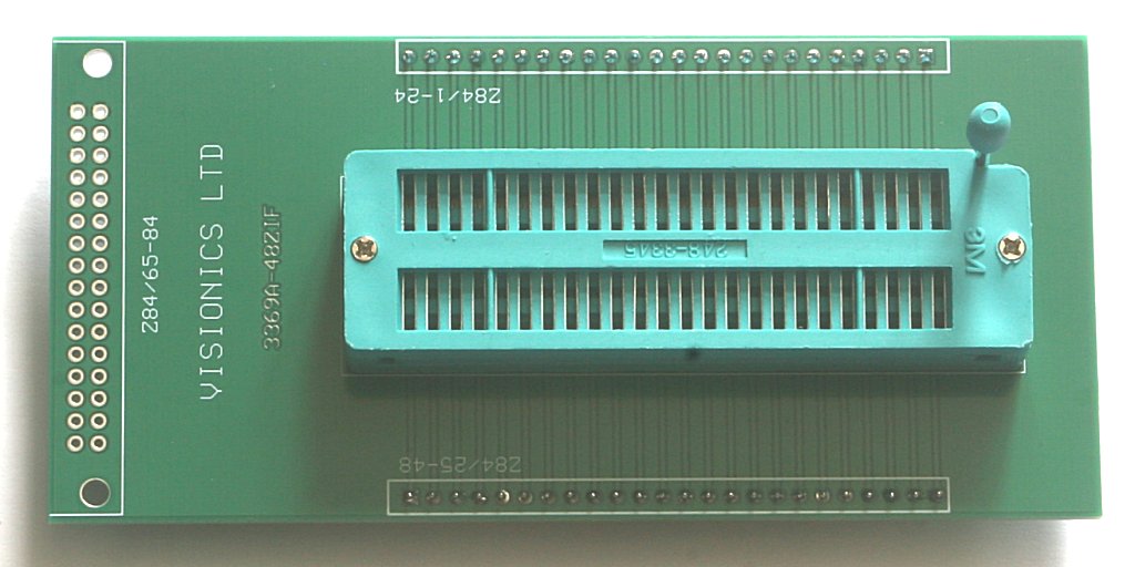
Adapters for testing analog circuis are less universal. Usually, they are usable only for one analog circuit family of operational amplifiers or some components. The adapters are inserted into headers an the mainboard. The mainboard has headers for 2x 34 + 32 pin adapter. Each adapter can have up to 96 pins. Each pin can be input or output or power or ground. Eight lines on the mainboard are used for control purposes, like interrupts or interrupt request, reset and test status. To each pin adaptor / mainboard can be connected a test instrument's probe or a signal from external source.
Fig. 3 - ZIF48 adapter
Maximal size of the adapter is 80 x 150 mm. Maximal allowed voltage is 24V.
Fig. 4 - ZIF68 adapter
The electronic circuit tester can quickly test various processors. Of course, a test program for the host computer must be prepared for each CPU or component to be tested.
Fig. 5 - CPU AM29116 with ZIF64 adapter on the mainboard