|
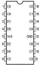
The next circuit (Fig.1) shows a standard nixie tube driving (IN-12 made by Sowiets) by
integrated circuit 74141. The integrated circuit 74141 receives data from asynchronous decade counter
7490.
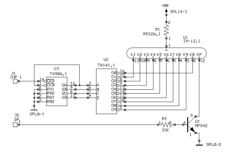
Fig. 1
The circuit in Fig. 1 has a disadvantage. In the event that circuit 74141 is without power and the Nixie tube is powered, the circuit 74141 will be destroyed.
You need to project the power supply to avoid this situation.
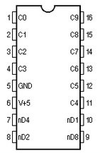
If a Nixie tube driver is not available, it can be driven by transistors.
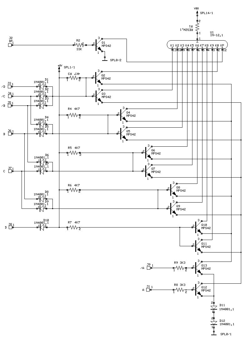
Fig. 2
While circuit 74141 had only logic inputs A, B, C, D, the circuit of Fig. 2 still
requires complementary inputs / A, / B, / C, / D. The connection in Figure 2 can be
modified by generally using any circuit (decoder, memory, counter), which outputs one
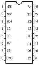
high state and nine low states. An example is a counter 4017 in the circuit of FIG. 3.
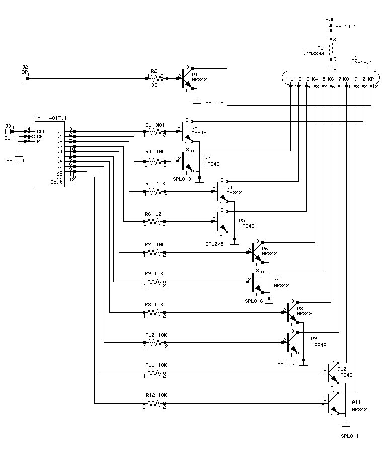
Fig. 3
The values of resistances in the bases of transistors must be calculated according to
the given situation (type of transistor, supply voltage, nixie type).
The disadvantage of this connection is the need to use ten resistors for base control
individual transistors. However, if we use a circuit (counter, decoder, memory) that will have an output
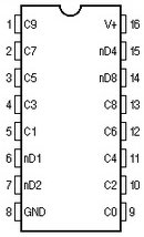
only one Low state and nine High states, we can change the connection from Fig. 3 as shown in Fig. 4.
The transistors are now driven into emitters and their bases are connected to a single common resistor.
The condition is that only one transistor will be switched on at a time.
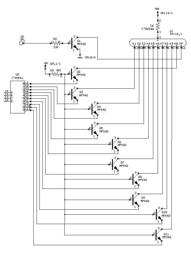
Fig. 4
Circuit 4017 and essentially no other circuit of the 4000 or 4500 series can be used in the circuit of FIG. 4 because these circuits are unable to provide sufficient control current.
|